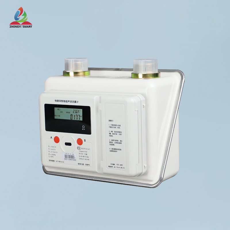
一、Product Summary
Dear users, thank you for using our membrane gas meter. Please read this instruction manual carefully before using it, so that you can easily use our products.
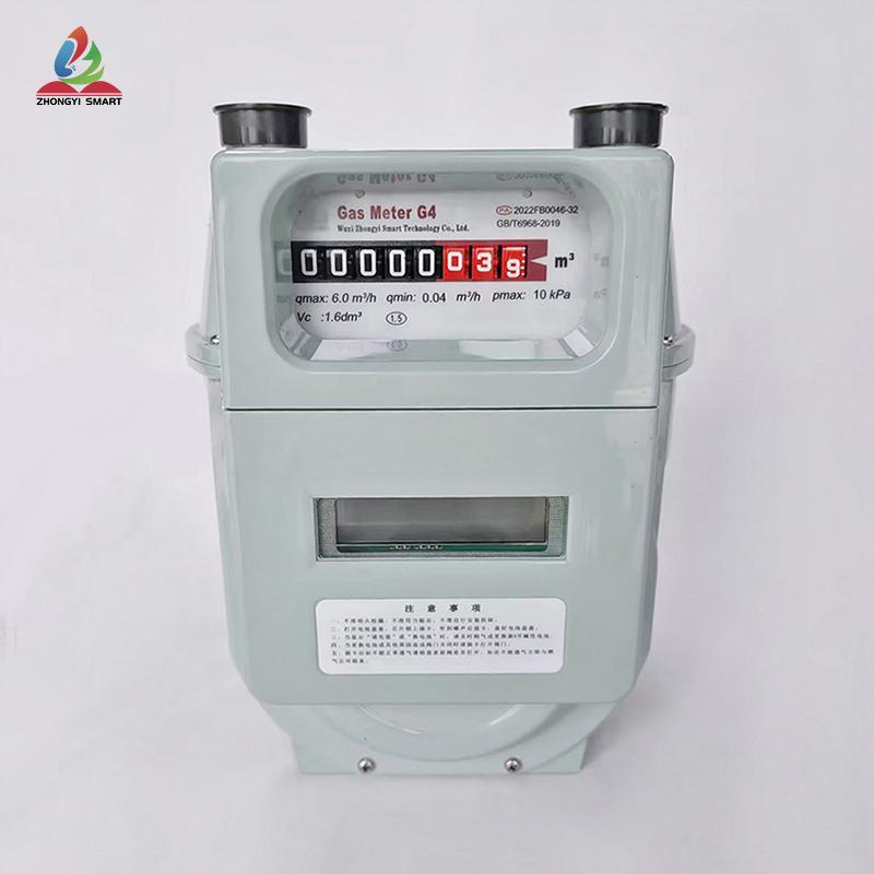
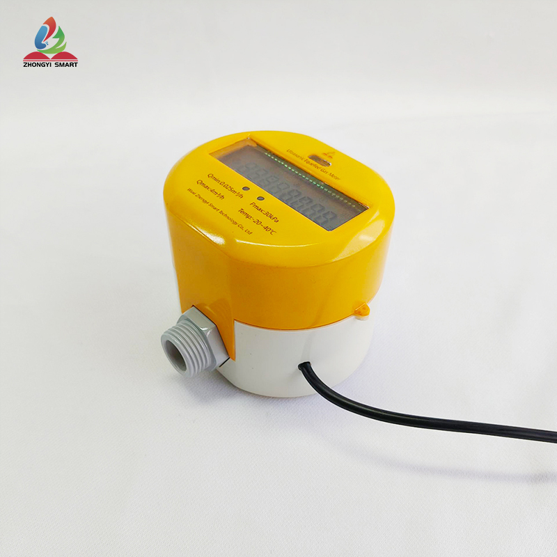
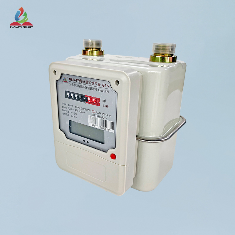
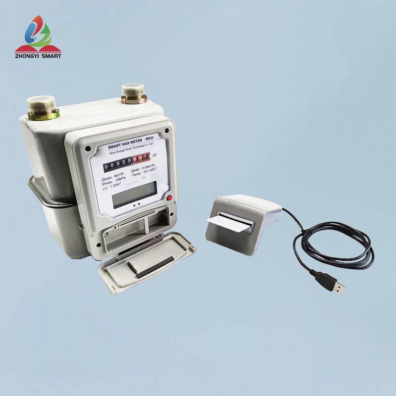
This product adopts aluminum alloy die-casting shell, special surface treatment process, strong anticorrosion ability, high sensitivity, accurate measurement and stable performance, and is suitable for flow measurement of natural gas, liquefied petroleum gas and other gases.
GB/T 6968-2019 Membrane Gas Meter
Verification Regulation of JJG 577-2012 Membrane Gas Meter
二、Working Principle
When the flowing gas passes through the gas meter, As a result of pipe friction and mechanism obstruction, There will be a pressure difference between the inlet and outlet of the gas meter, This pressure difference mainly pushes the diaphragm of the diaphragm gas meter to move in the metering chamber, At the same time, it drives the coordinated gas distribution of the gas distribution mechanism, So that the motion of the diaphragm can be continuously reciprocated, Through crank-rocker mechanism, This linear reciprocating motion is transformed into a circular motion, The circular motion then pushes the counter to rotate through the motion transmission mechanism to record the number of reciprocating motions of the diaphragm. As the diaphragm reciprocates once, a certain amount of gas is discharged, and the counter finally displays the volume of the measured gas through the conversion of the transmission chain to achieve the purpose of measuring gas.
三、Function List
|
Serial Number |
Functions |
Comments |
|
1 |
Metering function |
1. Accumulated flow of real-time reed counter |
|
2 |
Gas metering data history memory local |
1. For the latest 90 days, the measurement data is stored every hour 2. The latest 180 days, the measurement data is stored every day 3. Monthly storage of measurement data in the latest year |
|
3 |
Power supply |
The main battery is the normal power supply, and the other battery is the backup battery |
|
4 |
Main battery capacity level indication |
1. report that current battery capacity level suffix to the server in each metering data message uplink report 2. Low battery threshold: 20% and will trigger the uplink report of low battery capacity alarm message, which will be reported every 24 hours until the standby battery switch threshold. 3. Battery switch threshold: 10% capacity will trigger the backup battery switch. |
|
5 |
Backup the battery switch only in the following cases, otherwise use the main battery |
1. Pull out the main battery or the main battery does not exist 2. The power of the main battery meets the switching threshold (10%) 3. The backup battery switch is automatic, so it will never be powered off. |
|
6 |
Backup Battery Function |
1. Maintain local metering of water flow 2. measurement data history storage and maintenance proces 3. Spare battery life should exceed at least 7 days 4. When the power supply is switched to the backup battery, the backup battery switch alarm information will go up to the server to tell the switch that it has occurred. |
|
7 |
Backup battery protection during transportation |
Prior to field activation, the gas meter is only equipped with a spare battery, which is protected against consumption during storage or transportation at this stage |
|
8 |
Wireless/wired technology |
Lorawan/NBIOT/GPRS/RS485 |
|
9 |
Fixed time measurement data report |
1. Latest cumulative measurement data 2. Gas meter status: valve status/power supply 3. Battery capacity level 4. Downlink Signal Strength Indication RSSI/SNR |
|
10 |
Alarm Message Uplink Report |
1. Battery Capacity Low Level Alarm 2. Backup battery switch alarm 3. Valve fault alarm 4. Vibration alarm (the meter has a buzzer, which can realize sound alarm when vibrating and is generally used for earthquake protection) 5. High temperature alarm (alarm is not realized at present, only temperature is monitored, which is generally used for fire protection)
|
|
11 |
Downlink Configuration/Query |
1. Set/Query Periodicity of Periodic Measurement Data Report 2. On/Off/Setting/Query/Time of Fixed Time Measurement Data Report 3. Modify accumulated traffic data for calibration 4. Read the current accumulated traffic data 5. Read the battery capacity level 6. Valve Control Close/Open |
|
12 |
Screen digital display |
1. The screen displays four screens, and the screen can be cut 2. Display contents: current reading, electric quantity, balance, valve status, signal status, temperature, time and vibration reminder 3. Display mode: The button lights up and automatically closes after 5 seconds without operation, and the screen can be cut |
|
13 |
433 air leakage detection linkage valve closing |
1. Monitor methane in real time, and give an alarm if the concentration exceeds 5% LEL 2. Receive sensor data through 433 communication, and perform valve closing operation Communication distance 50m (recommended to be installed near gas meter) |
IV. Performance characteristics
1. Integrally forming by a full-automatic intelligent aluminum alloy large die casting machine;
2. The surface process adopts imported powder full-automatic intelligent electrostatic spraying technology, and the overall appearance is smooth, uniform, corrosion-resistant and paint-stripping-resistant;
3; The slide valve cover/valve seat adopts German fine grinding technology, and the movement component adopts imported materials to ensure measurement accuracy after long-term use;
4. Anti-countercurrent, anti-gas theft and anti-private dismantling
5. Technical Parameters
|
Technical parameter name |
Unit |
G1.6 |
G2.5 |
G4 |
|
Minimum flow |
M3/h |
0.016 |
0.025 |
0.04 |
|
Initial flow rate |
M3/h |
≤ 0. 003 |
≤ 0. 005 |
≤ 0. 005 |
|
Maximum flow |
M3/h |
2.5 |
4 |
6 |
|
Overload flow |
M3/h |
3 |
4.8 |
7.2 |
|
Cyclotron volume (Vc) |
Dm3 |
0.7 |
1.2 |
2 |
|
Maximum allowable error |
% |
(0.1 qmax ≤ q ≤ qmax) ± 1. 5 (qmin ≤ q ≤ 0. 1qmax) ± 3 |
||
|
Maximum working pressure |
KPa |
≤ 50 |
||
|
Pressure loss |
Pa |
≤ 200 |
||
|
Sealability |
KPa |
No leakage at 75kPa for 3 minutes |
||
|
Durability |
H |
Run for 2000 hours to meet the above performance indicators |
||
|
Ambient Temperature Range |
° C |
-10 ° ~ 40 ° |
||
|
Center distance of meter joint |
Mm |
130 |
||
|
Table joint thread |
Mm |
M30*2 |
||
|
External union thread |
DN |
DN15 |
DN20 |
|
|
Outline Dimensions (L*B*H) |
Mm |
168*124*220 |
172*135*225 |
195*152*250 |
|
Weight |
Kg |
1.71 |
1.85 |
2.17 |
|
Communication Support |
Lorawan/NBIOT/GPRS/RS485 |
|||
6. Product Structure and Size
|
|
G1.6 |
G2.5 |
G4 |
|
A(中心距) |
130mm |
130mm |
130mm |
|
B |
124mm |
135mm |
152mm |
|
L |
168mm |
172mm |
195mm |
|
H |
220mm |
225mm |
250mm |
| Product specifications | G1.6/G2.5/G4 |
| Maximum working pressure | ≤50 |
| pressure loss | ≤200 |
| Ambient temperature range | -10°~40° |
| Table joint center distance | 130mm |
| Communication support | Lorawan/NBIOT/GPRS/RS485 |


