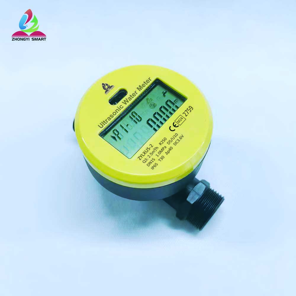
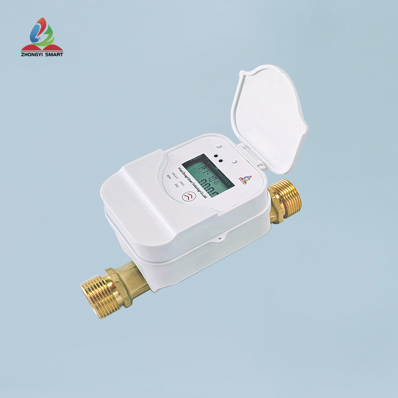
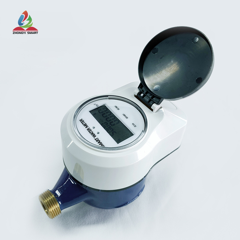
一、Product Summary
Dear users, thank you for using our multi-flow dry valve-controlled water meter. Please read this instruction manual carefully before using it, so that you can easily use our products.
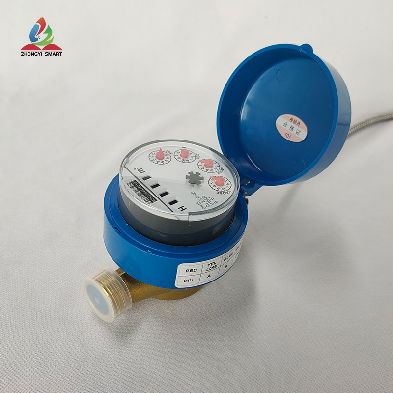
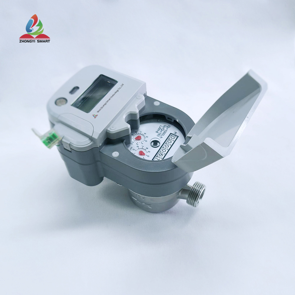
Multi-flow dry valve-controlled water meter is mainly a water inlet direction, through which water flows into the water meter movement and scours the impeller of the water meter, thus obtaining a kind of water meter for measurement.
The counter adopts dry counter, which can keep clear reading for a long time. Choose high-quality materials, reliable performance, small initial flow, high measurement accuracy, beautiful and durable appearance; Magnetic sensor is adopted, which has stable performance and high reliability.
However, it also has disadvantages. Because the stress points of a stream of water are relatively concentrated, the impeller of the water meter will be worn to some extent after long-term use, thus affecting the measurement and service life of the water meter.
Implementation standard: GB/T 778-2018 "Drinking Cold Water Meter and Hot Water Meter"
CJ/T 535-2018 "Internet of Things Water Meter"
二、Working Principle
The working principle of the rotor-type multi-flow dry valve-controlled water meter is that the water flow tangentially impacts the impeller from the water inlet of the watch case to make it rotate, and then continuously records the number of revolutions of the impeller through the gear reduction mechanism, thus recording the cumulative flow through the water meter.
三、Function List
|
Serial Number |
Functions |
Comments |
|
1 |
Metering function |
Accumulated flow of real-time Hall counter |
|
2 |
Water metering data history storage local |
1. For the latest 90 days, the measurement data is stored every hour 2. The latest 180 days, the measurement data is stored every day 3. Monthly storage of measurement data in the latest year |
|
3 |
Power supply |
1. Battery powered 2. External power supply |
|
4 |
Main battery capacity level indication |
The suffix of that current battery capacity level is report to the server in each metering data message uplink report |
|
5 |
LED indication |
Communication events; Screen Cutting Event |
|
6 |
Manual triggering (triggering varies according to different models) |
Button triggers an escalation event Magnet triggers report event Trigger 1 second switch screen Trigger 2 seconds to report data Trigger more than 9 seconds to restart the device |
|
7 |
Wireless technology |
Lorawan/NB/GPRS |
|
8 |
External Interface |
RS485/Mbus |
|
9 |
Periodic reporting |
1 The default period is 24 hours Latest cumulative measurement data Water meter status: valve status/power supply Battery Capacity Level Downlink Signal Strength Indication |
|
10 |
Timed reporting |
1 Fixed time (for example, 23:00, also configurable) triggers metering data reports every day, and the message payload is the same as the periodic report Latest cumulative measurement data Water meter status: valve status/power supply Battery Capacity Level 5LoRaWAN Downlink Signal Strength Indication RSSI/SNR |
|
11 |
Alarm Message Uplink Report |
Battery Capacity Low Level Alarm Backup Battery Switch Alarm Valve fault alarm |
|
12 |
Screen digital display |
1 Display content: current reading, electric quantity, balance and valve status (default valve opening status of non-valve controlled water meter) 2 Display mode: normally bright (low power consumption screen) |
|
13 |
Mode of transport |
In the transportation mode, log is closed, communication is closed, pulse is not metered, and the operation with minimum power consumption is maintained |
|
14 |
Antenna (Nb/Lorawan/GPRS) |
Built-in antenna (spring/soft antenna) External antenna (chuck antenna) |
|
15 |
Infrared Configuration (Optional, Default None) |
Infrared Setting/Read Table Parameters Infrared Update Program |
|
16 |
Communication mode |
Supported Band |
|
|
M66 (GPRS Communications) |
850/900/1800/1900MHz |
|
|
BC26 (NB Communications) |
B1/B2/B3/B4/B5/B8/B12/B13/B17/B18/B19/B20/B25/B26/B28/B66 |
|
|
BC35G (NB Communications) |
B1 @ H-FDD: 2100 MHz B3 @ H-FDD: 1800 MHz B8 @ H-FDD: 900 MHz B5 @ H-FDD: 850 MHz B20 @ H-FDD: 800 MHz B28 @ H-FDD: 700 MHz |
|
|
BG96 (NB/GPRS/CATM Communications) |
Cat M1/Cat NB1: LTE FDD: B1/B2/B3/B4/B5/B8/B12/B13/B18/ B19/B20/B26/B28 LTE TDD: B39 (For Cat M1 Only) EGPRS: 850/900/1800/1900MHz BG96-M Cat M1: LTE FDD: B1/B2/B3/B4/B5/B8/B12/B13/B18/ B19/B20/B26/B28 LTE TDD: B39 |
|
|
BC66 (NB Communications) |
B1/B2/B3/B4/B5/B8/B12/B13/B17/B18/B19/B20/ B25/B26*/B28/B66 |
|
|
Lorawan Newsletter |
CLASSA, CLASSB and CLASSC modes are supported, and the supported frequency bands are shown in the attachment |
|
|
RS485 communication |
Four lines: red +, black-, yellow A, blue B |
四、Performance characteristics
The engineering diameter of multi-flow dry valve-controlled water meter is generally 15-25mm, which has the characteristics of small volume, order-taking structure, light weight and low cost, and the error adjusting device is placed externally.
五、Technical Parameters
|
Caliber |
DN15 |
DN20 |
DN25 |
|
Minimum Flow (Q1) |
0.031 |
0.05 |
0.079 |
|
Boundary Flow (Q2) |
0.05 |
0.08 |
0.126 |
|
Maximum Flow (Q3) |
2.5 |
4 |
6.3 |
|
Nominal Flow (Q4) |
3.1 |
5 |
7.9 |
|
Range Ratio = (Q3/Q1) |
80 |
||
|
Maximum allowable error |
Q3 ± 2%, Q2 ± 2%, Q1 ± 5% |
||
|
Accuracy grade |
Class B |
||
|
Working pressure |
≤ 1. 6MPa |
||
|
Pressure loss |
≤ 0. 1MPa |
||
|
Level of protection |
IP65 |
||
|
Working water temperature |
0 ~ 30 ℃ |
||
|
Communication mode |
Lorawan/NB/GPRS/RS485 |
||
|
Power supply |
3.0 V |
||
|
|
|||
六、Product structure and size


| cal | DN15~25 |
| Range Ratio = (Q3/Q1) | R80~R160 |
| Maximum allowable error | Q3 ±2%, Q2 ±2%, Q1 ±5% |
| Accuracy grade | Class B |
| Working pressure | ≤1.6Mpa |
| Pressure loss | ≤ 0. 1MPa |
| Level of protection | IP65 |
| Working water temperature | 0~30℃ |
| Communication mode | Lorawan / NB / GPRS / RS485 |
| Power supply | 3.0V |


