1 product Overview
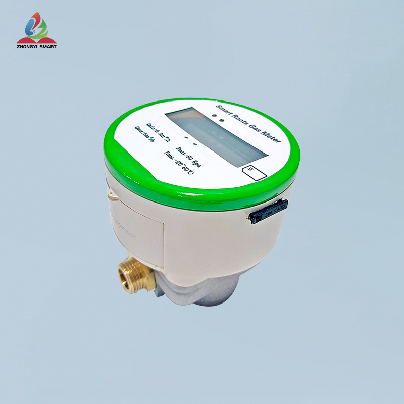
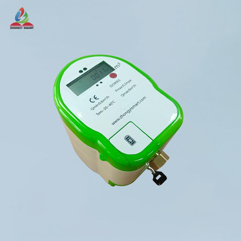
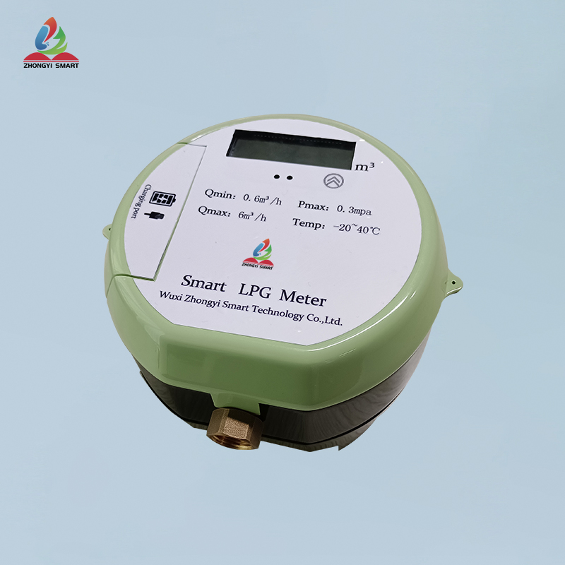
Dear user, thank you for using our company's non-valve-controlled Roots gas meter, please read this instruction manual carefully before use, so that you can use our products easily.
RootsGas Meteralso known as gas waist wheelGas Meter,There is a metering chamber in the housing, and there are one or two pairs of waist wheels that can rotate tangentially in the metering chamber. A pair of driving gears are installed coaxially with the two waist wheels outside the flowmeter housing, and they mesh with each other to make the two waist wheels Can be linked with each other, so as to obtain theA kind of gas meter.
Roots gas meters are mainly used for high-precision metering instruments for continuous or intermittent measurement of gas flow in pipelines. It has the characteristics of high precision, good reliability, light weight, long life, low running noise, convenient installation and use, etc.
2 working principle
RootsGas Meter, mainly composed of housing, conjugate rotor and counting device and other components. A pair of conjugate rotors installed in the metering chamber maintain the correct relative position through the precisely machined adjustment gears under the action of the pressure difference between the inlet and outlet of the circulating gas. Optimum working clearance is maintained between the rotors, between the rotor and the housing, between the rotor and the wallboard, and a continuous non-contact seal is realized. Every time the rotor rotates once, it outputs gas four times the effective volume of the metering chamber. The number of revolutions of the rotor is transmitted to the cumulative indicator counter through the magnetic seal coupling device and the deceleration mechanism to display the cumulative volume of the output gas.
3 function list
|
serial number |
Function |
Remark |
|
1 |
Metering function |
real-time cumulative traffic |
|
2 |
power supply |
1. Battery powered 2. External power supply |
|
3 |
Main battery capacity level indicator |
Report the current battery capacity level suffix to the server in every metering data message uplink report |
|
4 |
external interface |
Infrared serial port Baud rate 2400 no parity 8 data bits 1 stop bit |
|
5 |
screen digital display |
1 Display content: current reading, power, balance 2 Display mode: always on (low power consumption screen) |
|
6 |
RS485 communication |
Four wires: VCC, GND, A, B |
4 technical parameter
|
caliber |
unit |
DN15 |
DN20 |
DN22 |
DN27 |
|
Minimum flow (Qmin) |
m³/h |
0.3 |
|||
|
Maximum flow (Qmax) |
m³/h |
6 |
|||
|
work pressure |
Kpa |
≤50 |
|||
|
Operating temperature |
℃ |
-20~60 |
|||
|
communication method |
|
NB-IOT |
|||
|
Backup power supply |
V |
3.6 |
|||
|
maximum reading |
m3 |
99999.999 |
|||
|
minimum reading |
m3 |
0.001 |
|||
|
Quiescent Current |
μA |
<30 |
|||
|
Maximum operating current |
mA |
≤300 |
|||
|
data storage period |
year |
>10 |
|||
|
|
|
|
|||
| Minimum flow (Qmin) | 0.3 |
| Maximum flow (Qmax) | 6 |
| Operating temperature | -20~60 |
| work pressure | ≤50 |


