


1. Overview
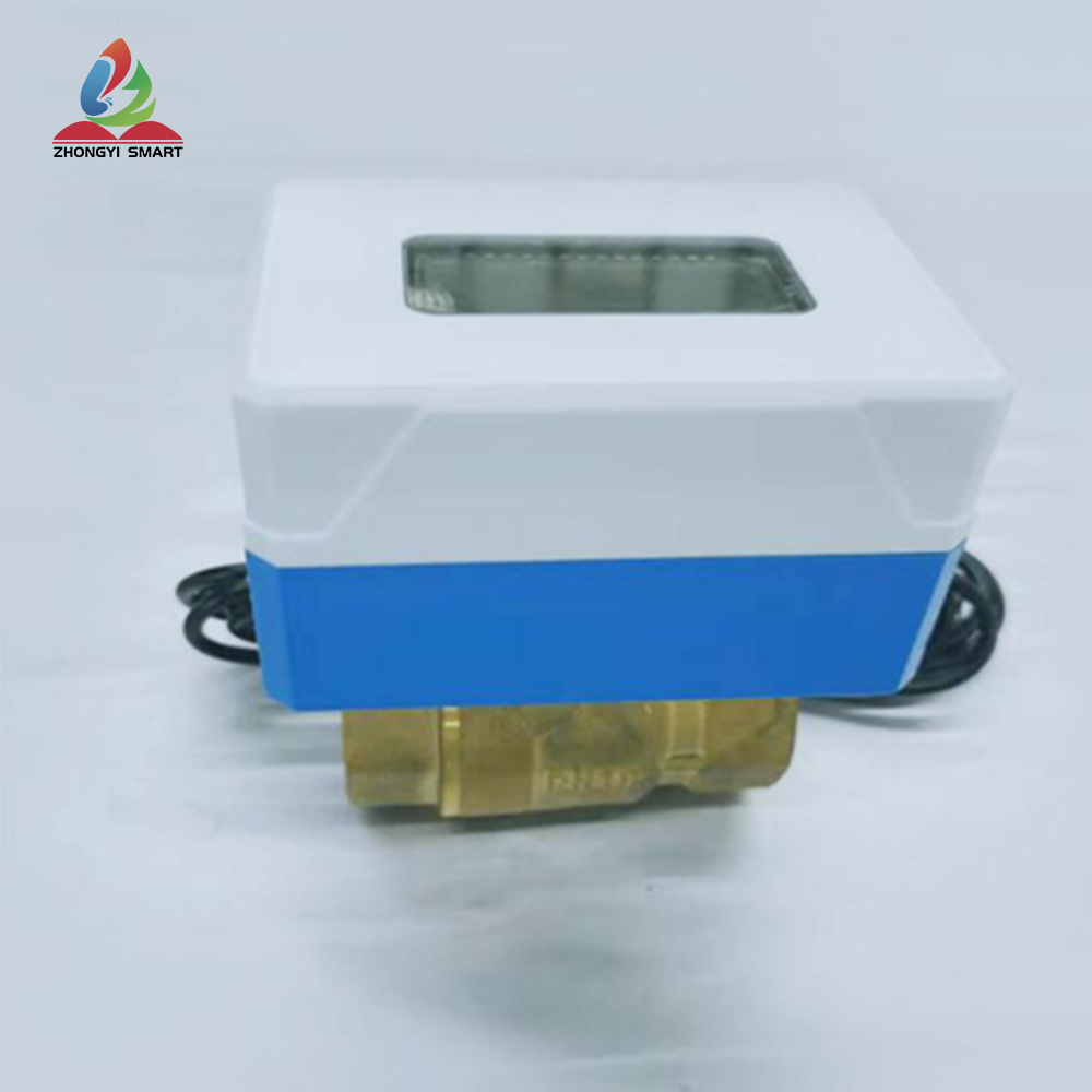
The ZYVALVE series are devices that provide remote valve control for water and gas. It uses LoRa wireless technology to achieve excellent space cover, installation easily. This document describes the technical specifications of the smart valve.
The smart valve ZYVALVE can be used in two scenario: an independent valve and a linkage valve. It is usually installed in a water or gas pipeline to control the gas or liquid in the pipe.
In terms of communication, it adopts LoRa wireless technology and works in Class B and Class C modes. When receiving a control command, it will perform switching valve action. When the valve is abnormal, it will report to the server to notify the error. The error generally is: half valve,
non-response valve
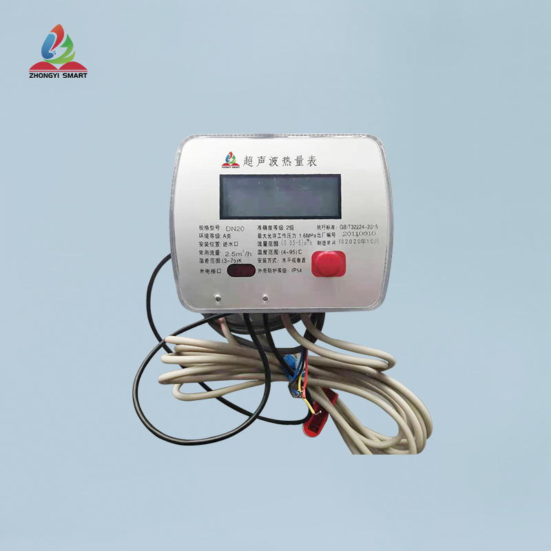
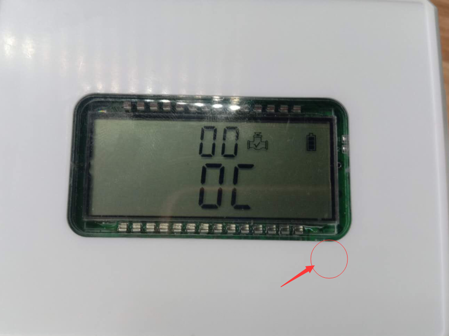
The screen shows the overall power supply of the valve, the working status code, the valve status etc.
2. Specification
2.1. Specification
|
Diameter |
DN15/20/25 |
|
Environmental type |
B |
|
Installation way |
Horizontal or vertical |
|
Connection way |
|
|
Working pressure |
<=2.6MPa |
|
Material |
Brass |
|
Electromagnetic environment |
E1 |
|
Type of valve |
Ball valve |
|
Environmental Temperature |
0.1 ~ 90 ℃ |
2.2. Operating condition
|
Temperature |
-20~70℃ |
|
IP Protection |
IP65 |
|
Power supply |
USB external power 3.6V ½ AA Lithium battery, 8000mAh |
|
Consumption |
10-15UA |
|
Battery life* |
Typical useful life 3 years |
2.3RF performance
|
Frequency band |
470MHz~930MHz Support global LoRaWAN frequency plan |
|
Transmitting power |
Max 19dBm |
|
Limited receiving sensitivity |
-140dBm |
|
Antenna gain |
Peak -2dBi@868/915MHz, -4dBi @470MHz |
2.4. Use interface
|
LEDs |
Red and green indicator RED: Flashes in communication GREEN: Lights up when the magnet is close |
|
Sensor |
Full limit Hall sensor, trigger screen, wake-up device, manually switch valve |
|
USB external power supply |
Standard USB |
2.5. Working mode
1) Periodic reporting mode: This mode can report the valve status in the period according to the preset.
2) Valve alarm mode: This mode can perform valve detection and report alarms according to the preset timeout time and whether the valve is in place.
2.6. Other features
Device battery level
Device status indication
2.7. Installation
1) The pipe or connection nuts should meet the corresponding caliber of valve.
2) Tie the leak-proof tape on the connection point to ensure no leakage after installation.
3) The USB external power supply should be fixed and routed.
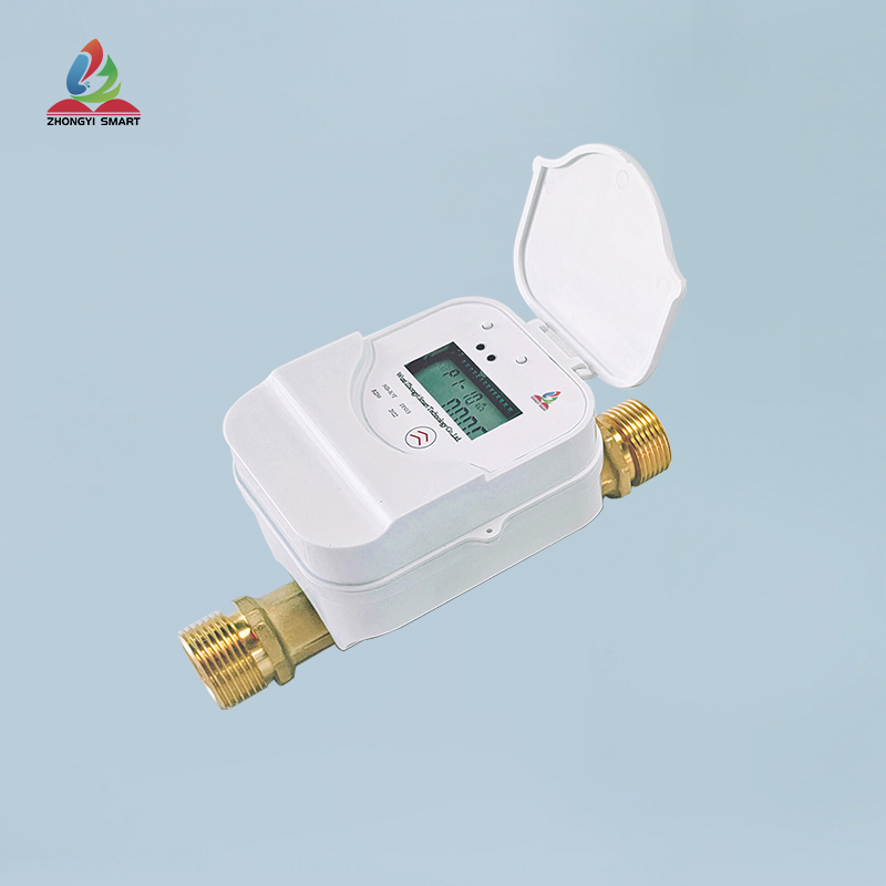
4) When installing, keep the valve screen facing up or into the visible line of sight to ensure that the screen is clearly visible.
5) The installation environment should ensure good signal, waterproof and other conditions for use in the scene.
3.Operation
3.1. Transportation mode
|
USB power |
When receiving the device,please remove the bundle for wire |
|
Battery |
During transportation, the battery is disconnected with main board. After receiving the device,please take out the battery,and plug it in. |
3.2. Powered on
When the device is powered on at any time and the voltage is greater than 2.8V, the device will automatically connect the network. Judge whether it is in the ownership status, and decide whether it will work normally or sleep according to the status.
3.3. Ownership status
It is recommended that users bind the device to the server before powering on the device.
After binding, the device is powered on and automatically connected to the network, it will determine the ownership status with the server, and then the device can work in the default working mode
3.4. Device not owned
If the device is not bound, when it is powered on, it will try to report the unowned status to the server multiple times after being connected to the network. After the red LED is off, the user can also perform the binding operation as soon as possible.
But if the device receives the server's non-ownership confirmation, the device will enter the sleep mode first. It is recommended that the user bind the device to the server before powering on the device.
If the device receives the ownership confirmation, it will jump into the ownership state, and then the device can work in the default working mode.
If the device reports to the server the unowned status multiple times and does not receive any response (owned or unowned) for more than 3 minutes, it will also enter the sleep mode. The sleep mode will wake up again by resetting.
3.5. Default working mode
In working mode, as long as it detects that the valve is opened or closed for more than 20 seconds at any time, the device will send an alarm message and the screen will display the fault code.
Within a 3-hour period, the device will also send a heartbeat message to report the ownership status, and detect battery power information. In addition, the device will self-check the hardware status every 24 hours.
3.6. On-site installation mode
At any time, if the user wants to obtain whether the wireless signal quality at the installation location is good or not, they can trigger the on-site installation mode.
In the on-site installation mode, the device will communicate with the server (Red and blue LED will flash alternately during the interaction), and will be indicated by the LED after finishing.
If there is no network in the current location, you will not be able to enter the on-site installation mode, and will automatically try to reconnect to the network.
The on-site installation mode can be triggered by the following operations. Take a magnet, keep close to the lower right corner of the valve screen, when the green light is on, hold it for 2 seconds, and the red light will flash once, thus completing a communication interaction .
Notes: Refer to the table in Appendix 1 for the definition of LED status.
3.7. Device unbinding
Note: Please do not unbind the device unless necessary!
The unbinding operation can transfer the ownership of the device.After the device triggers the unbinding, the server will allow the device to bind and belong twice after receiving the request.
The unbinding operation can be triggered by a magnet.
3.8. Switch valve manually
If the user wants to manually switch the valve on the device, he needs to hit a magnet, keeps it close to the lower right corner of the valve screen, and observe if there will be a number bounce on the top of the screen. When the bounce reaches 06, remove the magnet. If the current valve state is open, it will close the valve; if the current state is closed, it will open the valve. The following figure shows the position of magnet activation.
3.9. Change battery
Open the battery cover, take out the battery, unplug the battery cable, replace the battery with a new one, put the battery in, and close the cover.

| Nominal diameter | DN15/DN20/DN25 |
| Environment type | Class B |
| Installation method | Horizontal or vertical |
| Connection mode | Threaded connection |
| working pressure | <=2.6MPa |
| body material | brass |
| electromagnetic environment | E1 |
| Temperature adaptation | 0.1 ~ 90 ℃ |
| Valve type | globe valve |